May15, Final Design for the Head of my Scarecrow(Subtractive)
- I've finally decided to make the head of my Scarecrow in Hexagonal shape.
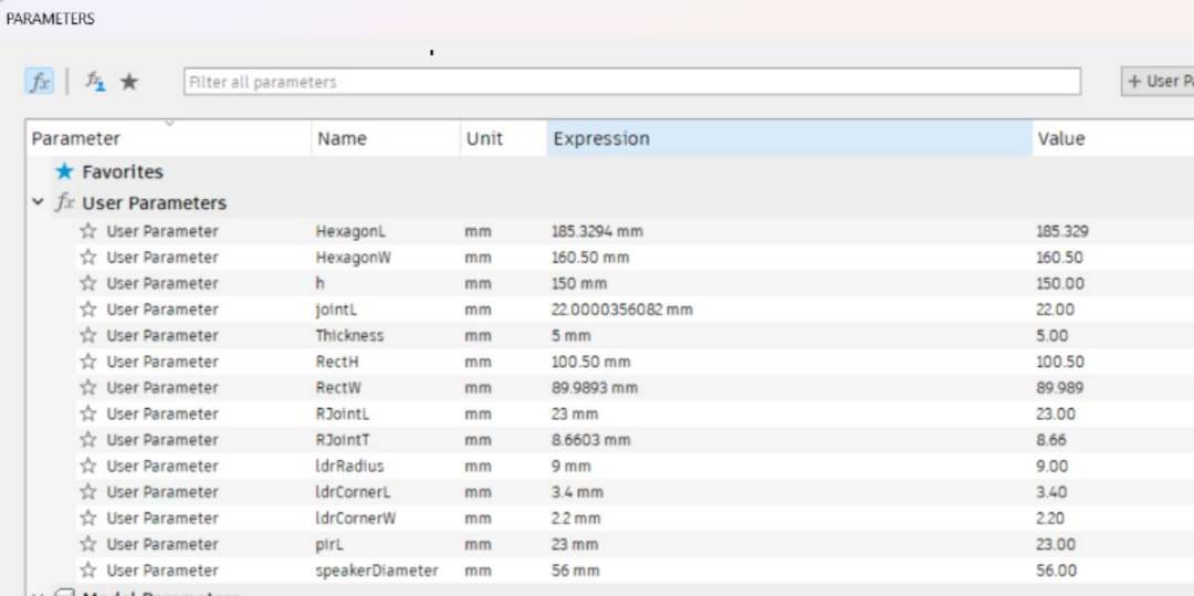
- I designed using Fusion 360.The Parameters I used.
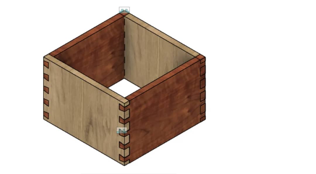
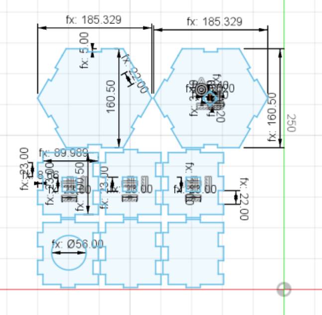
- I used two Hexagonal shape with joints. Then six rectangle with joints like shown below. Used parametric design.Used Fillet in the whole provided for LDR.
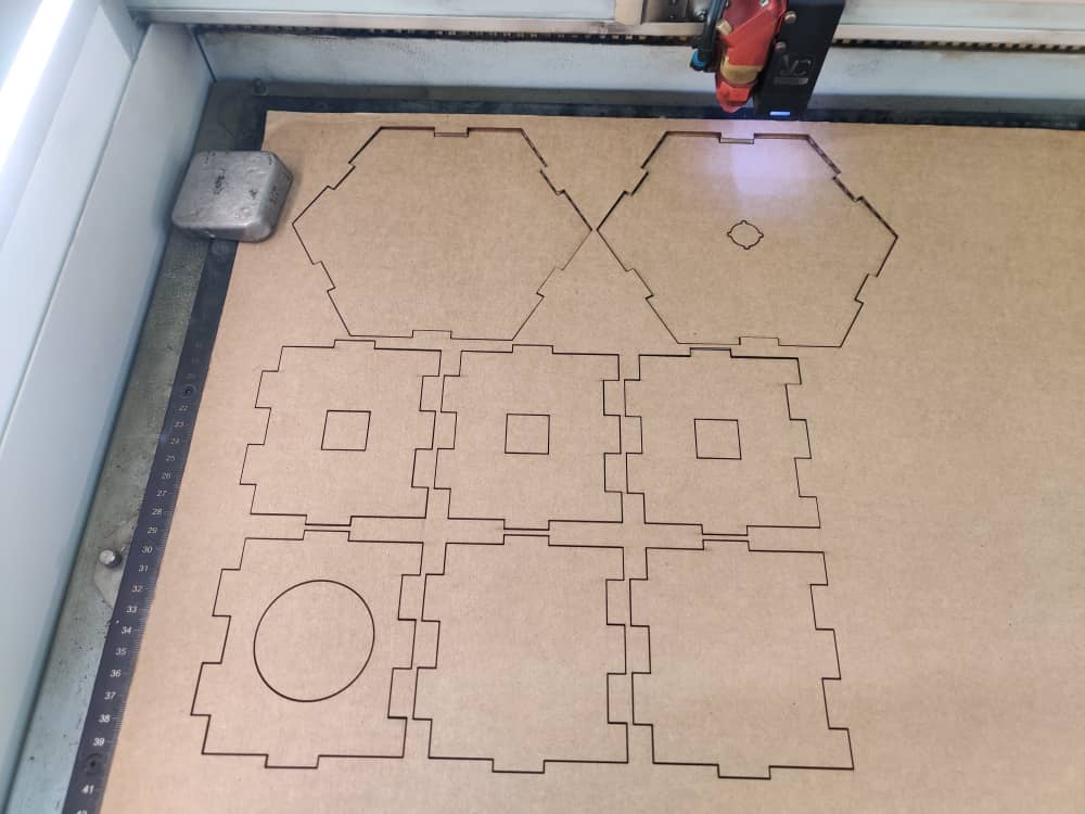
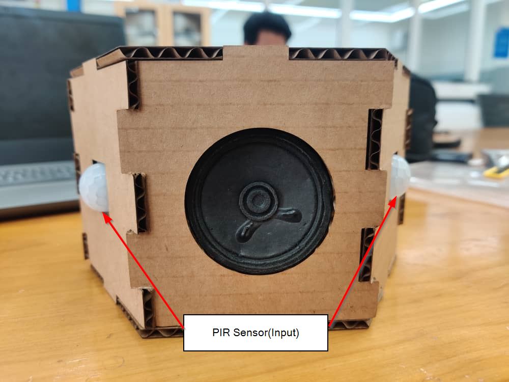
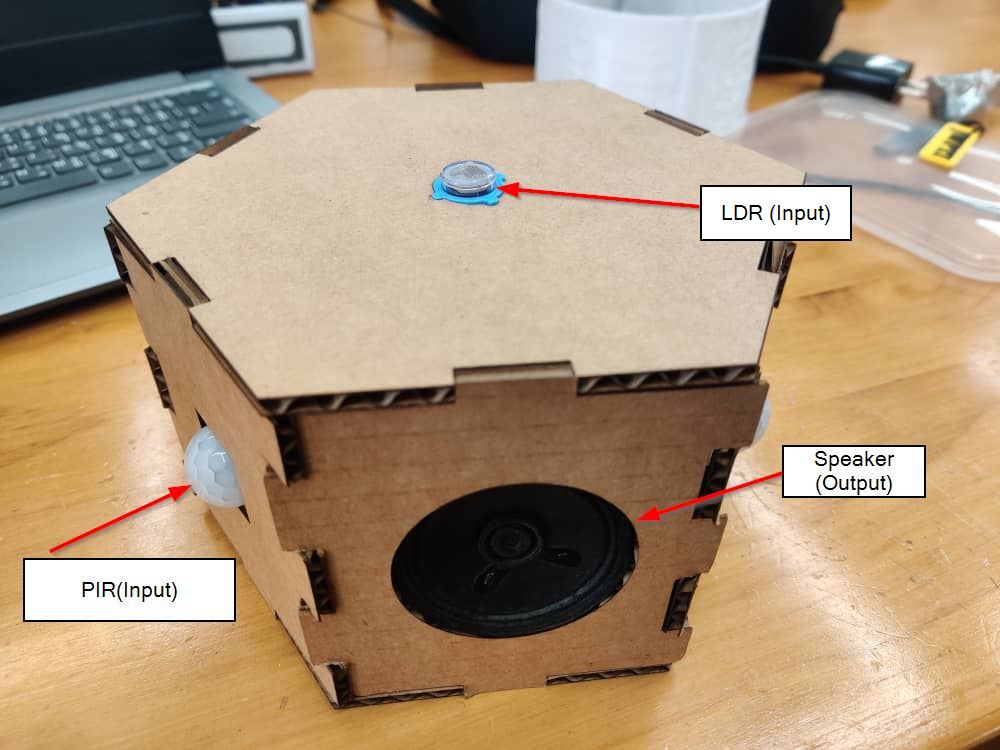
- I cut the design in Laser cutter machine, first for trial I used cardboard to cut out the pieces. I'll be cutting the actual one in Ply board. The fit for all the input and output design was Okay.
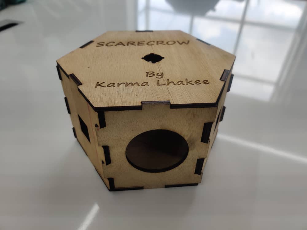
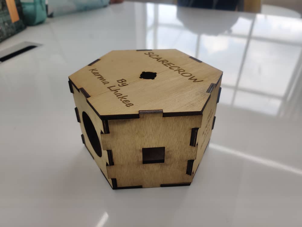
- Finally got the plyboard and I cut my design and this is how it turned out.
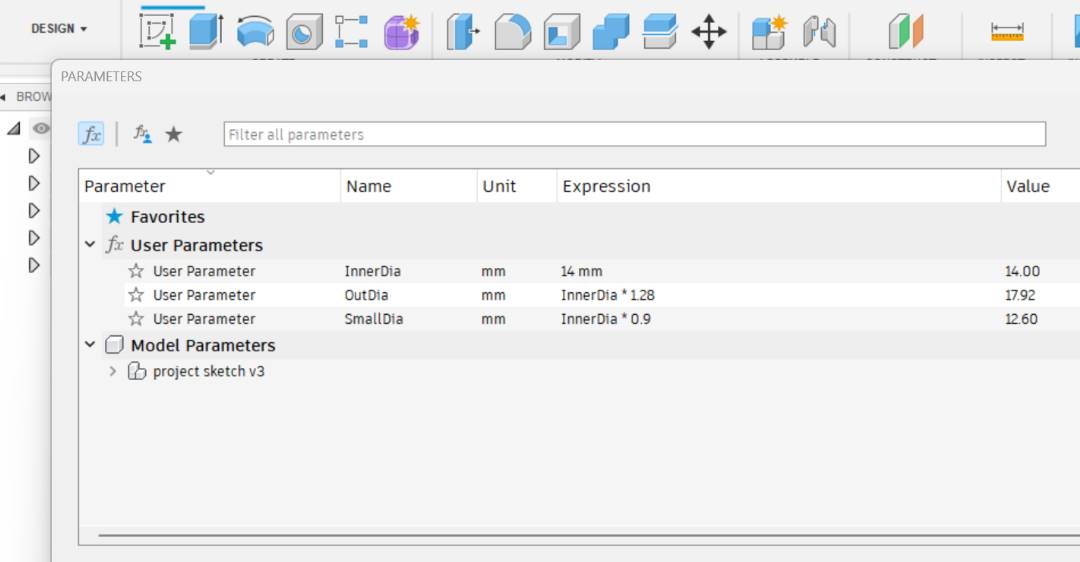
- Since the LDR sensor I had seemed open and fragile, I designed to design a cover so that it doesn't get damaged while placing the LDR in the Housing/Head.
- These are the Parameters I used.
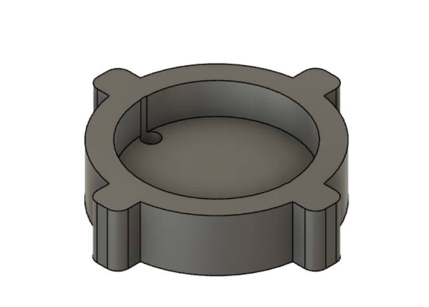
- I used filets,combined and cut through functions.Here is a short clip of how I designed.
- This is how the final design turned out.
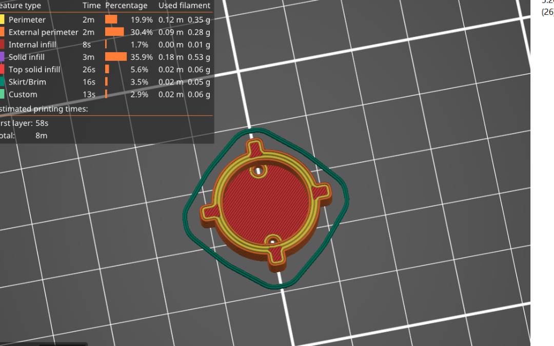
- I used prusa slicer to convert the design to g-code which is read by the 3D printer.
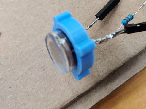
- It took me 4 mins to print the design. It turned out great, fit perfectly.
- I'm going to put the housing/head of the scarecrow on the the tripod so that where ever it will be placed, it can be stable.
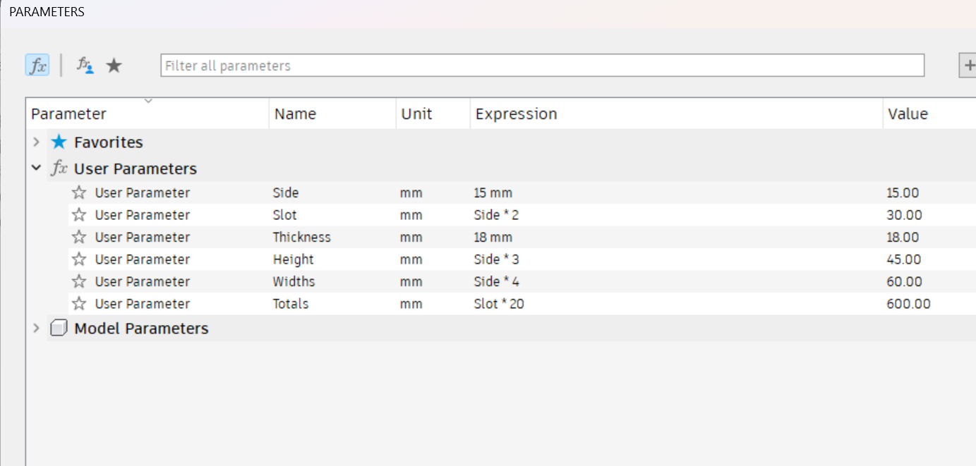
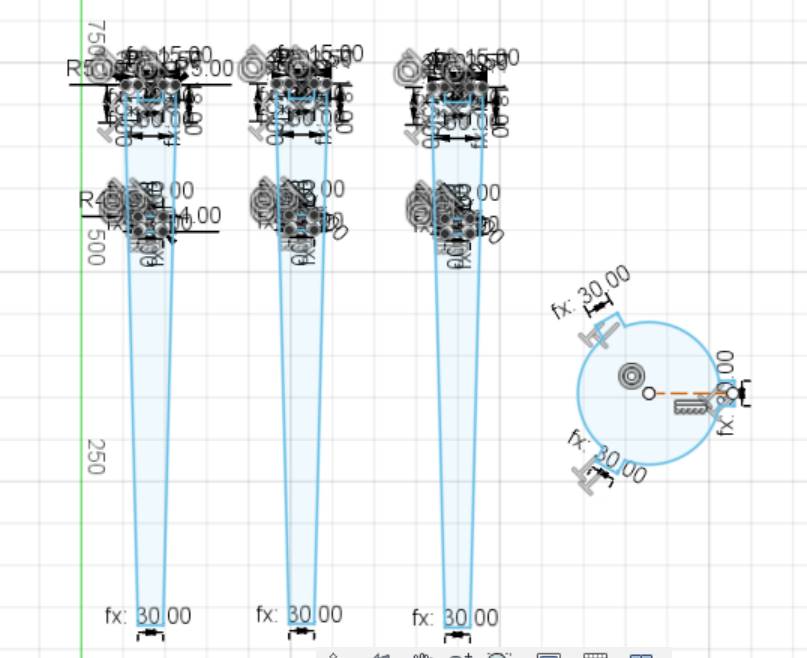
- This is the parameters that I used.
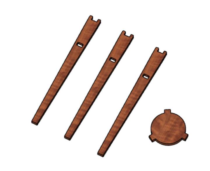
- This is the design I made.
- I'll be cutting the design using the Shopbot. Since this whole week the shopbot wasn't free, I couldn't cut the my tripod. I'd be using leftover wood pieces in our lab.
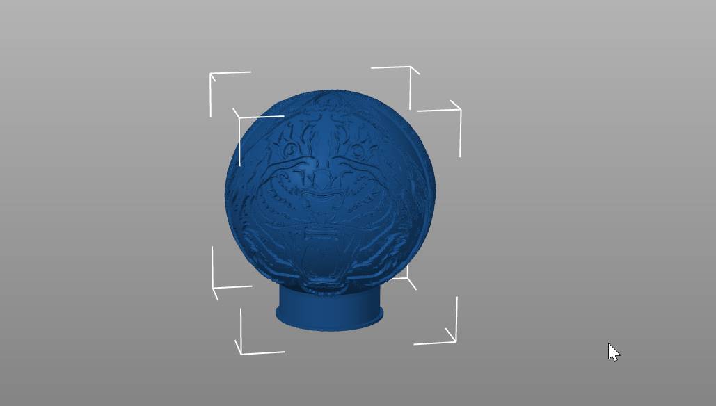
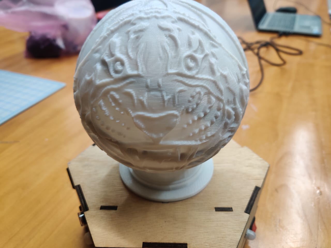
- For designing this, I learnt about a website called Lithoplanemaker from Rinchhen and designed the LED lamp with a Tiger image popping up
- A Lithoplane maker is a tool or software that allows you to create lithoplanes, which are 3D printed objects that use light and shadow to create a detailed image.
- The 2nd image shown above is the 3D printed LED lamp which turned out perfectly.
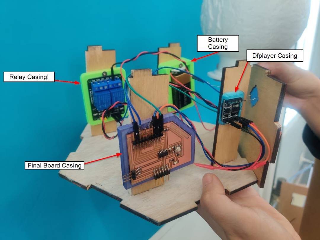
- Designed a casing for the relay, battery, dfplayer and the final board in the Autodesk Fusion 360.
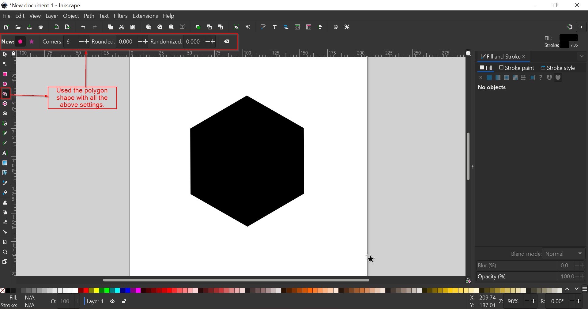
- Create a New document. I selected the Polygon shape with six corners. Arranged the shape so that its in the middle of the work page.
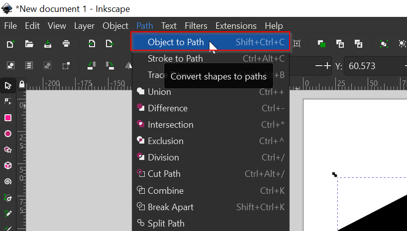
- Selected the shape and converted it to Path by going to Path, then selected Object to Path option.
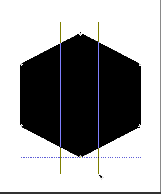
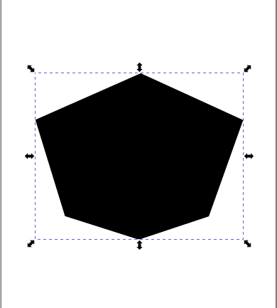
- I clicked on the "Edit path by nodes" tool, selected the two nodes in the middle and enabled the transformation handles to scale these nodes down a little bit to get my desired shape.
- Did the same with the bottom corner nodes to get my desired shape for my Logo.
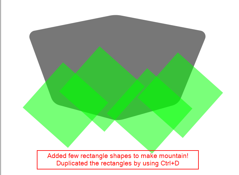
- To create some mountains for the background, added rectangle shape and duplicated it.
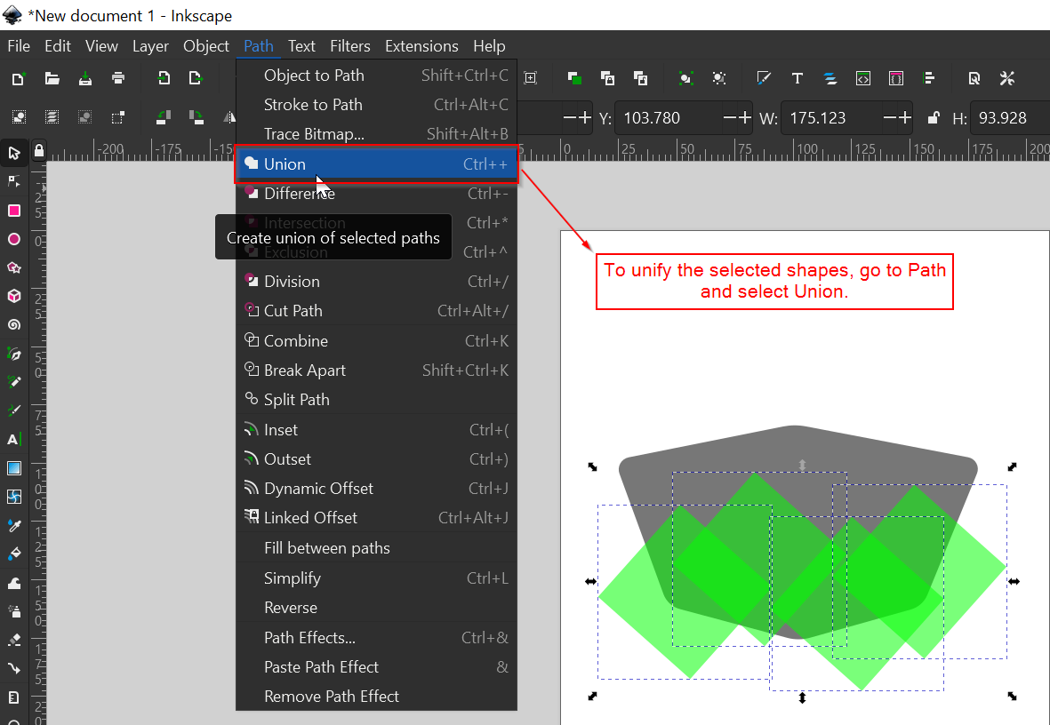
- Selected all the duplicated shapes (Shift+Click) and unify them all together by going to path and Select "Union"
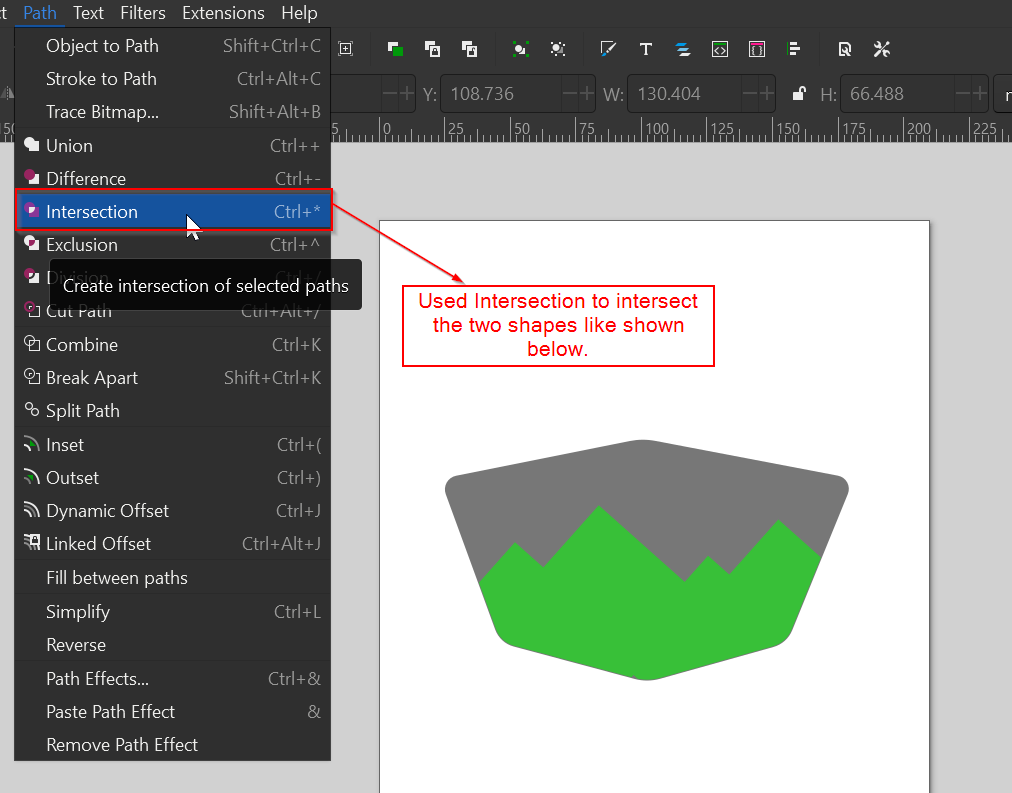
- Then selected the images to be intersected and intersected the images.
- Like wise used several tools like "Path Effects","Difference","Trace Bitmap","Text", played with the textures and filters. Finally got the design I wanted.
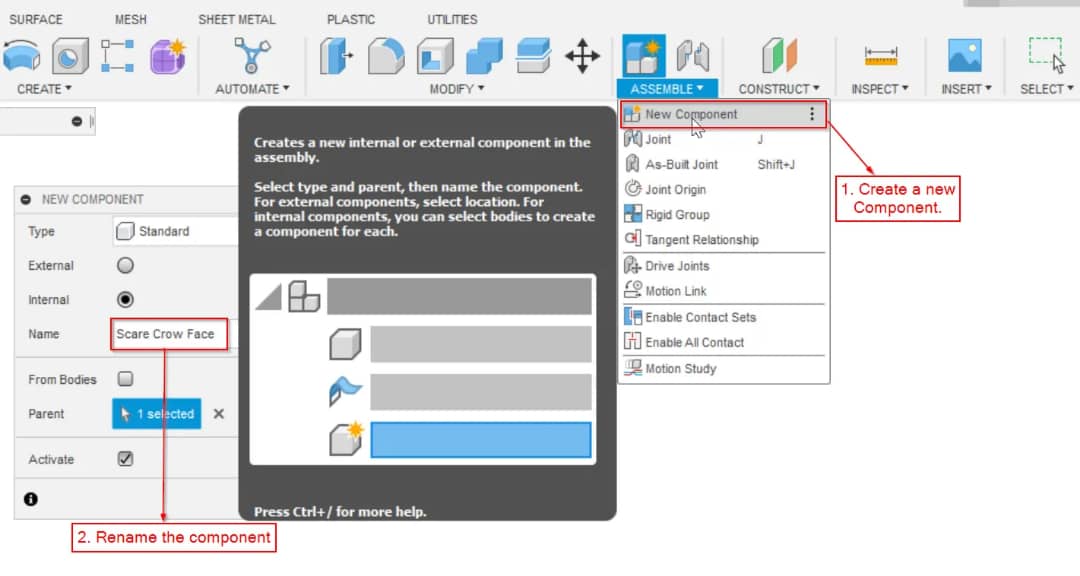
- First clicked on the new component and renamed the component.This will help keep the files organized and easier to manage.
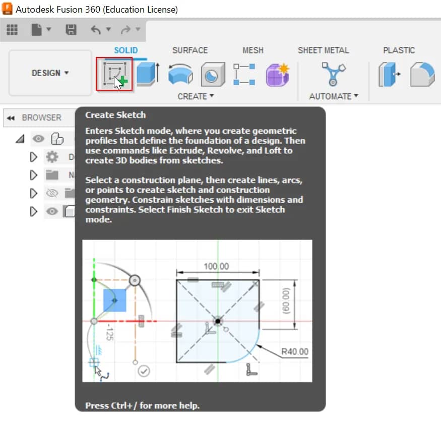
- For most Fusion 360 workflows, we'll have to start by creating a 2D sketch that is turned into a 3D body. I started new 2D sketches with the "Create Sketch" feature located in the toolbar or the Create Menu.
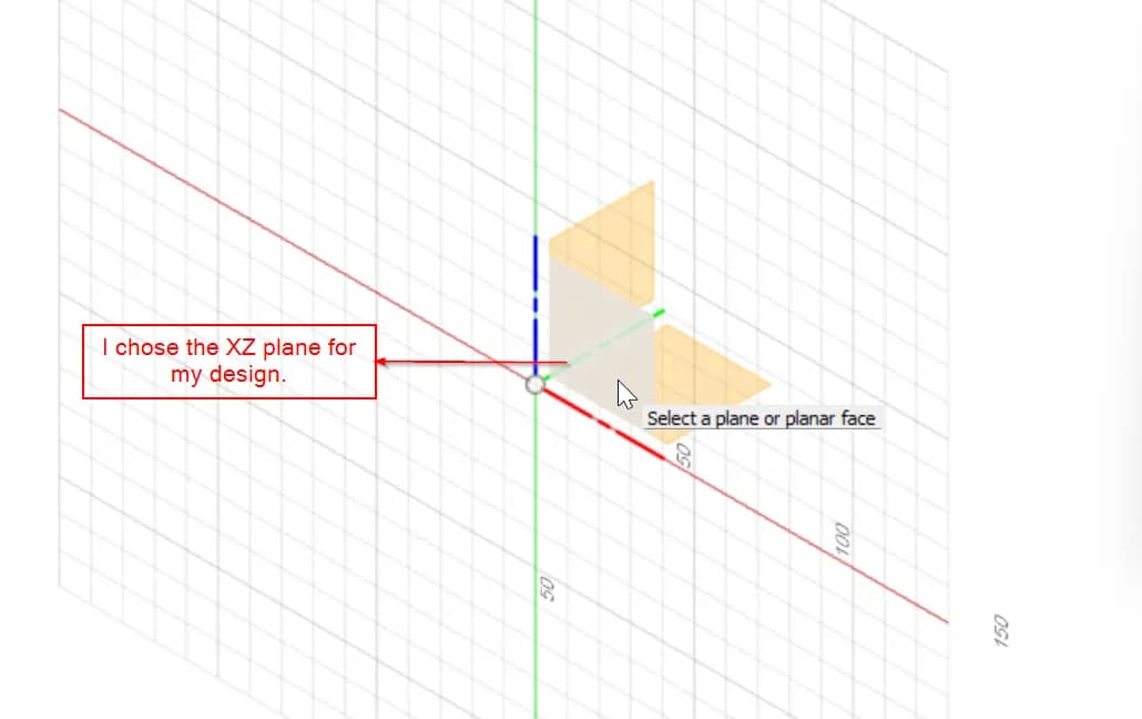
- We are then prompted to select one of the origin planes. These origin planes correspond to our X,Y and Z axis.In this case i selected the bottom XY origin plane.
- We'll see that our view is automatically reoriented to look directly at the sketch. We will now see a Sketch tab in the toolbar. The sketch tools are contextual and will only appear while in an active sketch environment.
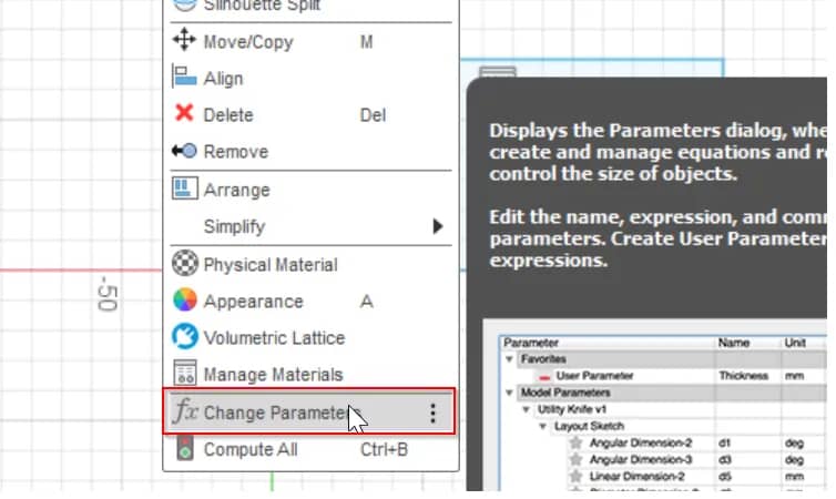
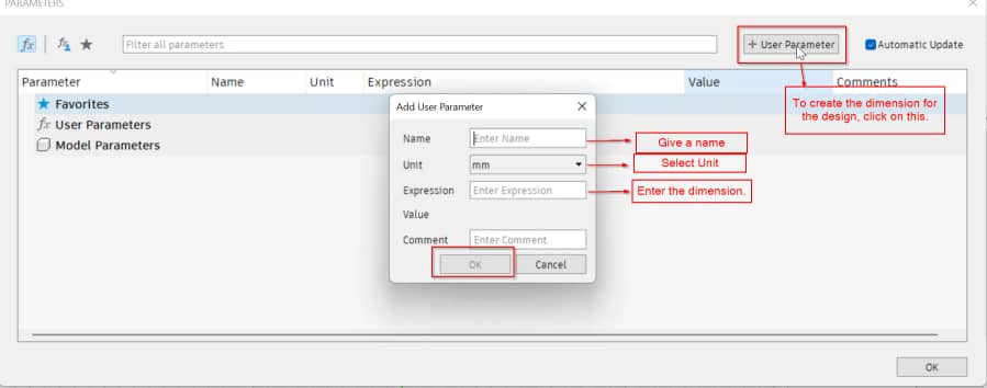
- Before I started sketching, First I set the Parameters by choosing the "Change Parameters" from the tool barr.
- To create the Parameter, click on the "User Parameter" and start naming the parameter and giving dimensions.
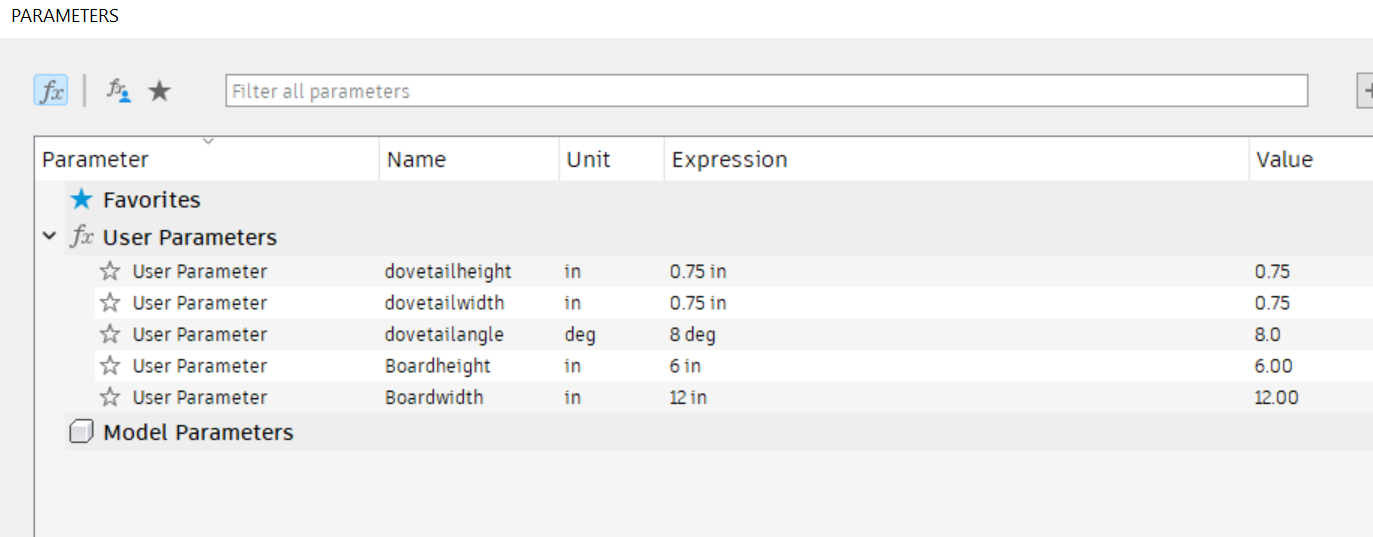
- Shown below is the Parameter that i decided to use. Setting parameters make designing much easier.
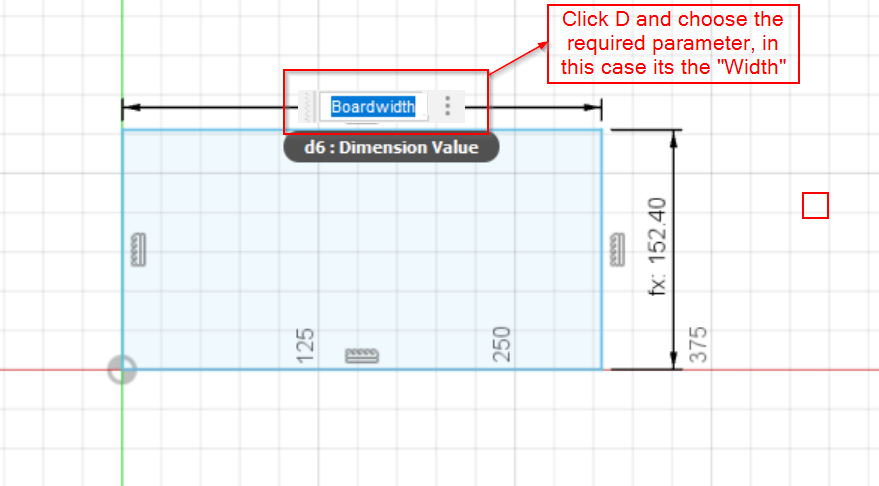
- After setting parameters, I started sketching by choosing the rectangle tool. Then gave the dimensions using Parameters.
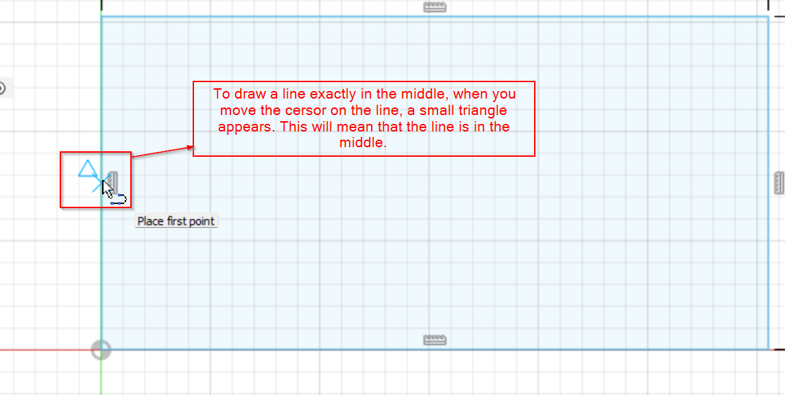
- Then I drew a line in the centre for reference to draw the dovetail joint.
- Then used the "Line" tool to draw the dovetail. Assigned the dimensions of the dovetail by using the parameter
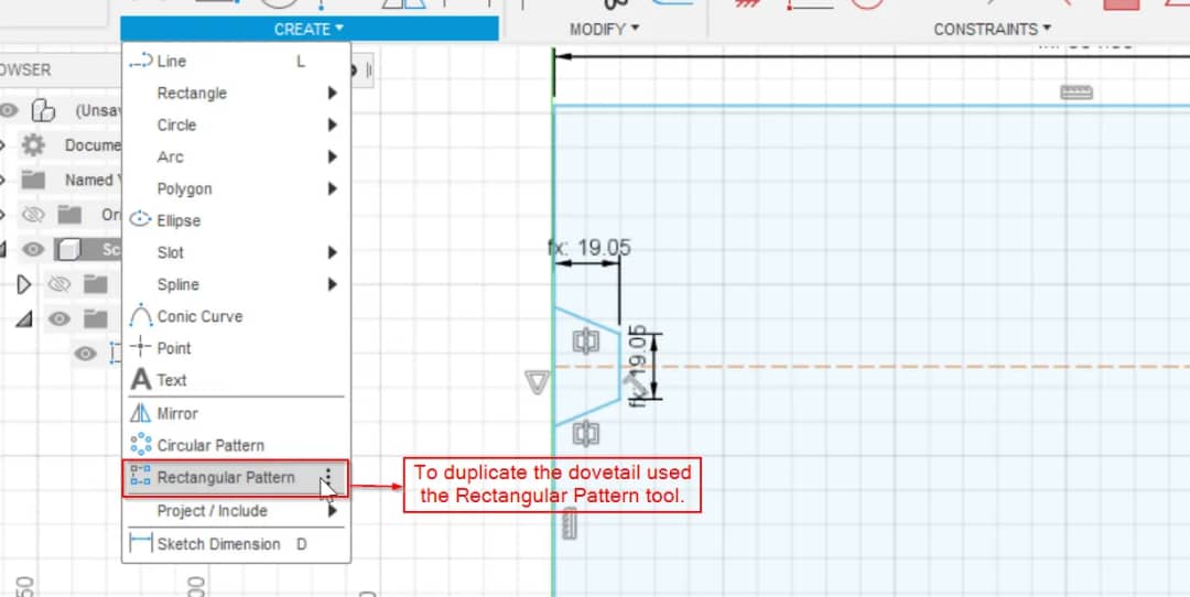
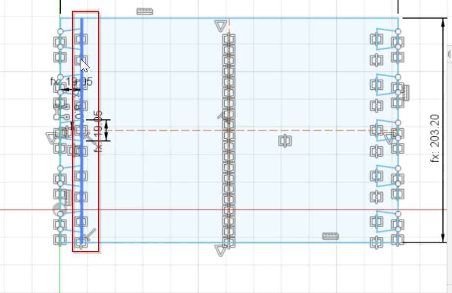
- After that needed to duplicate the dovetail so used the "Rectangle Pattern".
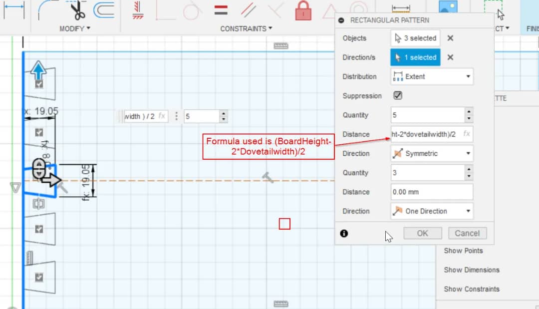
- To make my design comfortable and easier to work with, I set a formula for duplicating the dovetail.
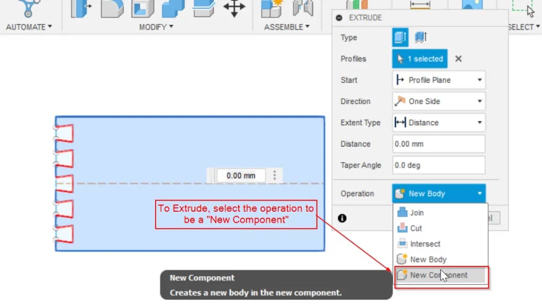
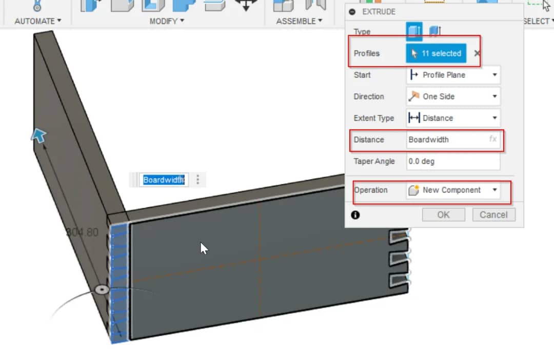
- After duplicating the dovetail, I click on "finish sketch". Then used the "Extrude" command to see the 3D sketch.
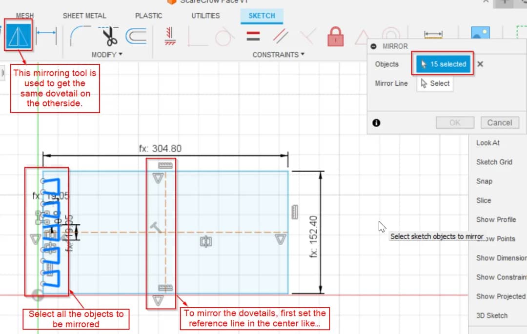
- Needed the dovetail in the other side of the plane. To do so used the "Mirror" tool.
- Then used the "Extrude" tool on the other side of the dovetail too.
- Now for the Pin board, I went back to the Sketch and drew a line.
- Then I used the "extrude" command for the Pin board and used parameters to give the dimensions.
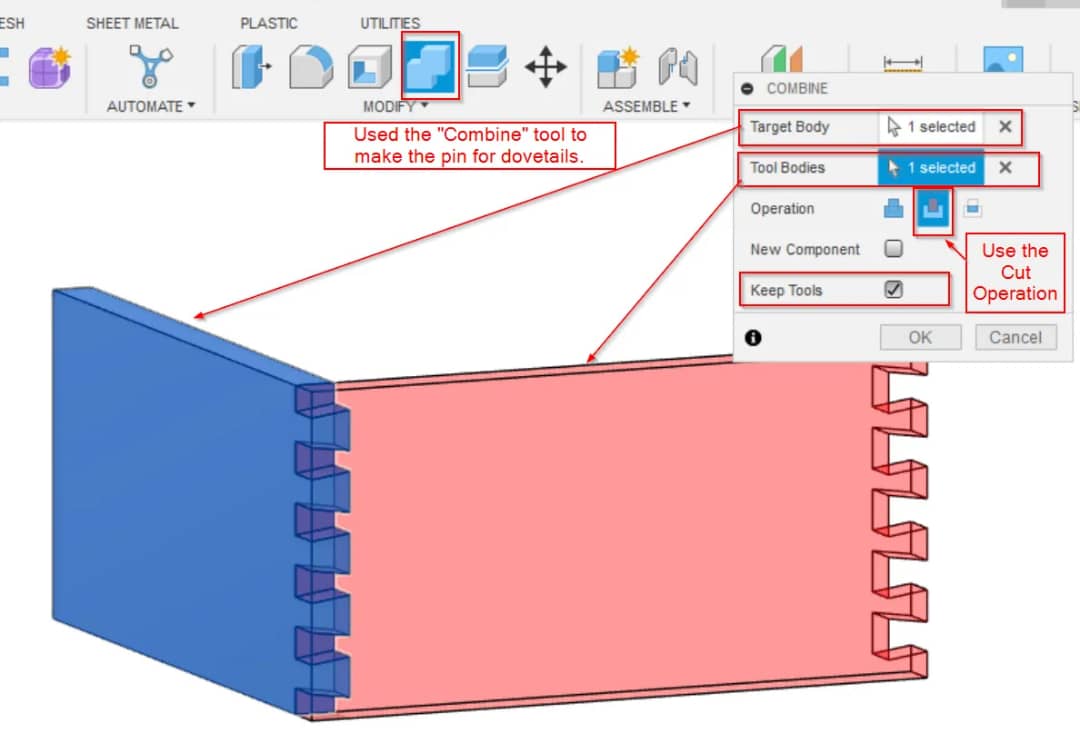
- Used the "Combine" tool to get the joints in the pin board.
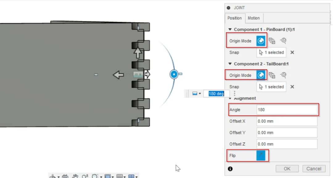
- Then I used the "Joint" tool to get the other plane of the Pin board.
- Did the same for the Dovetail Board. Hence I could achieve the 4 sides of the Box.
- LDR Cover
- Tripod Stand
- Head of my Scarecrow
Designed and 3D printed the cover for LDR sensor(Additive)
Designed A Tripod as the Body.
Designed A LED Lamp to be placed on the Head
Designed and 3D printed casing of Electronic Components.
Designing Logo for My Final Project using Inkscape

Modelling the Scarecrow Head with Fusion 360
I designed the head of my Scarecrow using Fusion 360 for my final project.